Shell: EXO-140 … 145
The PETG shell carries the 66 tiles, the hub, the battery and the five cameras. It is five printed parts: the crown
(EXO-140), the front band (EXO-141), the back band with the hub pod (EXO-142), the splice tabs (EXO-143) and the
battery cover (EXO-144). A sixth printed part, the headband (EXO-145), holds it on the head against the pins
(headband). The source is exo/shell_v1.py. Its outputs are out/step/EXO-14x.step (head frame),
out/stl/EXO-14x.stl (print orientation) and out/shell_v1_report.json (every check, the standoff table, the cable
list).
uv run python -m exo.shell_v1 --slice # ~15 min on 20 cores; --slice adds CuraEngine time and mass
It is built from the tiles as made: out/cap_layout.json gives each tile's frame and design, out/pcb/cap/boards.json
each design's outline, M2 holes and IN/OUT FPC connectors and the chains, and out/pcb/cap/placement.json every part. The hub comes from out/pcb/hub/hub_geom.json and the
cameras from out/pcb/camera/placement.json. Change a board and rebuild; never edit the outputs.
Wall
A tile's stack, out from the scalp:
- the pogo pin (the scalp 6.2–7.7 mm from the tile's face);
- the tile, 1.0 mm;
- the tallest part on its outer face: the FPC connectors, taken as 1.9 mm with the flip actuator and the cable's first bend.
Part heights are datasheet maxima taken from the placement.
The wall is one ellipsoid layer, as close to the head as the stacks allow. At every outline corner of every board, the
stack must clear the inner face by at least 0.5 mm, measured as a true 3D distance. The tiles alone would allow
12.4 mm, but the rim, the hub pod, the camera cradles and the cable lanes under the pod are laid out for 16.5 mm, so
that is the floor (D_SI_MIN): the inner face 16.5 mm and the outer face 19.3 mm off the scalp. The wall is
2.8 mm thick: seven perimeters, solid, so 1.3 mm of it stays under the deepest cable channel.
Standoffs
There is a standoff on each of the 132 hole sites, two per tile. Each one runs along the tile's normal from the shell's inner face down to the tile's outer face.
The standoff has two parts:
- Neck. Ø4.4. It stands inside the 2.2 mm keep-out that the placer leaves round every hole, so it touches no part.
- Body. Ø7, past the parts.
Each board is fixed with an ISO 7380 M2 button-head screw, put in from the scalp side. The Ø3.5 head sits among the pins and clears every scalp-face pad by at least 0.25 mm. The screw cuts its own thread in a Ø1.7 pilot in the PETG. There is no heat-set insert: an M2 insert needs a Ø3.2 hole, which would leave 0.6 mm of wall in the Ø4.4 neck.
Every tile takes two M2 × 6, with 5.0 mm of thread in the standoff.
Every pilot keeps at least 0.6 mm of PETG under the outer face, or under the floor of a channel where one runs over it.
Cables
There is one 0.5 mm FFC per link:
- along each of the 16 chains, each tile's OUT (J102) to the next tile's IN (J101): 50 links;
- each chain's first tile (J101) to a hub port: 16;
- each camera to a hub camera port: 5.
All are 12-way.
Behind every FPC connector, a 4.5 mm slot through the wall starts at the connector mouth. The cable bends straight up through it. Where a standoff is in the way, the slot moves along the cable or to one side, or folds back over the connector.
On the outside the cables lie in channels cut 1.5 mm into the outer face, laid as a harness in two layers:
- Chain links go first, each on the shortest path over the face that keeps clear of the cables already laid. Where the crown is too crowded for that (9 of the 50), two links lie flat one over the other in the channel.
- Camera and chain-head cables go next: the cameras first (their cradles are fixed and their lanes under the pod narrow), then the chain heads longest first, to the hub ports the assignment gives them (least total length). They don't cross each other: they share a channel, stacked flat on an earlier hub cable's centre line (up to four), or stay clear of it, and gather into trunks into the pod. A cable that would come out longer than the longest stocked jumper crosses the chain links square instead of going round them. The deepest stack is eight cables (1.2 mm).
- Every channel keeps 1 mm off the other boards' slots and the camera cradles, and its edge stays at least 1 mm inside the rim. Each path is pulled taut into straight legs: a flat cable turns by folding, not by bending in its plane.
- A channel is cut through whatever lies under its path, the headband's link bosses included (five camera cables and
one chain head run over them). Each groove is cut along its path's Douglas-Peucker line (
channel_line); the report keeps that line asweb.fpc[].cut, beside the routedpts, andexo/wearer.pydraws each cable on it, at the channel's floor and its stack level. At its ends the drawn strip stays square to its connector, slot or camera notch. - Open:
exo.wearer's rest check finds the edges of four camera FFCs 0.1-0.4 mm in the shell at 8 points (none of their centre lines): CAM3, CAM4 and CAM5 where the strip turns from the cradle's notch into its channel (the drawn strip turns in its plane there; a real FFC folds), CAM2 and CAM5 on the last leg to the pod. Widen the channel's start and end, or fold the strip in the drawing.
Controller and camera cables enter the pod through a slot in its wall facing each of the hub's 21 ports, then drop to the edge connector. Four camera ports are on the pod's bottom wall, so the rim drops 21 mm below the pod's lowest corner. That leaves room for two cable lanes under the pod.
Every link has identical bottom-contact HCTL connectors at both ends, wired pin n to pin n. Between two identical
connectors that mapping needs an opposite-side-contact (Type B) jumper whatever the route; the cable takes its one
half turn as a fold at a slot. fpc in the report lists each link's path and order length (path, slot rises, 3.5 mm
in each connector, +10 %, rounded up to 10 mm; where that passes the longest in stock, 400 mm, but leaves at least
10 mm of slack, 400 mm), and fpc_order gives the totals:
| link | count | way | jumper lengths to order (mm) |
|---|---|---|---|
| tile → tile (chain) | 50 | 12 | 70 – 160 |
| chain head → hub | 16 | 12 | 80 – 400 |
| camera → hub | 5 | 12 | 240 – 400 |
Hub pod
The hub sits on the back midline at head z = −31.0 mm, checked here against the tiles. Its scalp face is 6.56 mm off the headform at the centre, so the REF and BIAS pogo pins (the tiles' KH-205580-DZ) see 6.95 mm to the scalp, the middle of the pin's working range.
The pod is a box over the hub, 3.5 mm bigger than the board on every side so the cables can turn down into the edge connectors. The hub hangs from its flat ceiling on four standoffs with M2 × 6 screws. Any board standoff whose wall the pod takes away stands on a pillar up to the ceiling.
On top of the ceiling sits the battery compartment, for a 1S pouch of at most 70 × 45 × 9 mm: the certified cell of hub § power (≥ 2,500 mAh, ≥ 5 A continuous, its own PCM and NTC), for the hub's 1.88 A (2.25 A peak) with five cameras running. The pocket was sized on the MaxAmps Lipo-2000-1S-Pack-10 it replaces. The cell lies with its long side across the head, inside a 72 × 47 × 10 mm pocket. It is moved as far up the pod as it fits. EXO-144 closes it, held by four M2 × 5 screws into M2 × 3 heat-set inserts.
The antenna. The helmet's one radio is the hub's ESP32-S3-MINI-1U. Its flex antenna (Molex 146153-0050,
34.9 × 9 mm) is glued in a 0.3 mm recess on the inside of the pod ceiling, in the strip below the battery compartment,
long side across the head, and its 50 mm cable plugs into the module's U.FL socket. The ceiling is the part of the pod
farthest from the head. The build checks that the antenna is ≥ 3 mm from the cell in plan view (the pouch detunes
it) and ≥ 14.2 mm from the scalp, the distance the SAR exemption at 13 dBm needs (regulatory § 2);
out/shell_v1_report.json → hub.antenna has the figures.
USB-C. The receptacle is on the hub's bottom edge. A 14 × 8 mm tunnel runs straight down from it through the pod wall and opens on the outer face below the pod, at head z ≈ −83 mm, low on the back of the cuff (11 mm above the hem). The 3D view draws the port level and half-way up the cuff. Putting the real port there would need a panel-mount receptacle in the shell wall, wired to the hub.
Cameras
The five EXO-450 boards sit in cradles on the outer face, in the cuff zone, at azimuths 4°, 84°, 122°, −122° and −44°:
each is moved round the head from its nominal 0°, 72°, 122°, −122°, −72° (CAM_SHIFT) until its cradle clears every
tile's cable slot by a cable's width. Each board rests on a 1 mm ledge round its
edge, with its back parts in the recess over the shell. The walls round the board are:
- closed on the top and the right;
- notched on the left for the camera tail, and at the bottom for the hub cable.
Two nubs on the top wall and one on the left wall hold the board in, and the cuff's knit holds it too. The board has no mounting holes.
Seams and printing
- Crown seam. The crown is cut on a tilted plane (10°) near z = 68 mm. No plane misses every standoff, so each standoff the plane would cut stays whole on the crown, on a tongue of wall round it, and the band gets the matching notch.
- Band seams. The band splits front and back on two vertical half-planes that meet nothing.
- Splice tabs. Tabs, 1.2 mm thick, bridge all three seams on the inner face, clear of the boards. They are epoxied in.
Print orientation:
- The crown prints dome down, so its standoffs grow upward and its tongues are on top.
- The bands print upside down on the crown-seam plane.
Every shell part has more than 2 % of its area in downward faces steeper than 50°. They are printed with tree supports, and that is how they are sliced. The tabs and the cover print flat without supports.
The rim follows the head 10 mm under the beanie line, then drops over the back under the pod. Donning is checked as one puts on a helmet with a low back: back first, then the front rolled down. Along that path the rim, the board faces, the screw heads and the hub stay clear of the head, and the pogo pins, at full travel, press at most 1 mm into the hair.
Headband (EXO-145)
Why. Every pin pushes the shell off the head. With the 70 g KH-205580-DZ, linear from zero at its 8 mm free length,
the layout's gaps give 0.21-0.60 N a pin, 432 N in all. The pins push along the tiles' normals, so their sideways
parts cancel in the shell; what is left is a lift of 0.54 × the total (233 N), through the middle of the head. The
knit beanie holds about 35 N. The headband is designed for 150 N of pins (PIN_LOAD): the soft pin's preloaded spring gives 113 N, 130 N at
the top of its tolerance (pin RFQ), and the pin-force bench confirms the force.
At 150 N the lift is 81 N.
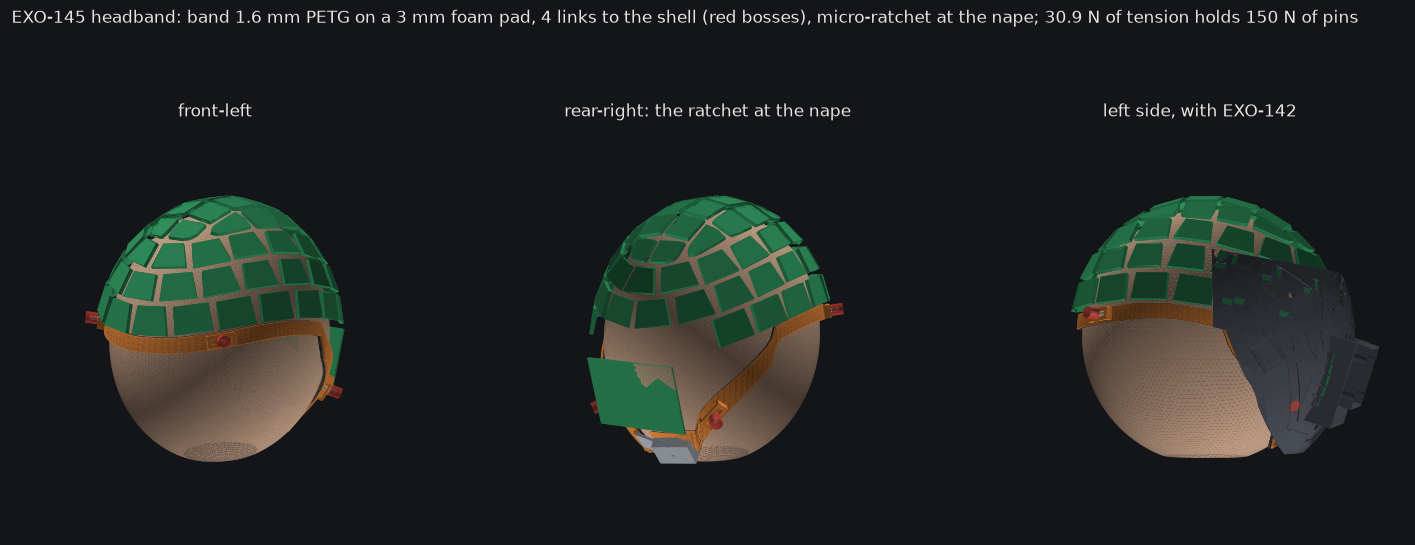
Shape. A 1.6 mm PETG band on a 3 mm self-adhesive closed-cell neoprene pad, inside the shell's 16.5 mm gap, below ring 1. Its path is generated from the parts round it: at every degree of azimuth, its lower edge is 1 mm above the shell's rim and its upper edge 2.5 mm under the lowest pin, screw head, board edge or the hub. So it runs round the brow (z 6-17 mm, 11 mm wide: the window between the rim and ring 1), above the ears, then down behind the ears to a 22 mm cradle under the occiput, below the hub (z -87 to -65 at the back midline). It is 636 mm long, at least 10.5 mm wide, and 22 g. All of it is under the shell, so the knit, the hem, the cuff and the cameras do not change.
The pad and the band lie on the wearer's skin, not on the head ellipsoid: the scalp mesh of exo/wearer.py (the
fitted MakeHuman head the rest checks use), offset along its normal by 0, 2 and 3.6 mm (Scalp). Above the rim
the skin is on the ellipsoid; under the occiput it is not, and the nape bulges up to 6 mm out of the ellipsoid where
the cradle's lower edge lies. Each cross-section is a polyline of seven points across the band, so the 22-33 mm
cradle follows the skin's curve, and the bridge legs at each link stand from inside the band wherever it curves
away under them.
Ratchet. The band is open at the nape (azimuth 166-178°, 15 mm). A commodity micro-ratchet helmet buckle (the "micrometric" chin-strap buckle) closes it: the receiver on the band's right end, the toothed tongue on its left end, each held by a 20 mm webbing loop and two M3 × 6 screws into a 2.4 mm block on the band. Push the tongue in to tighten, one tooth at a time; pull the buckle's tab to release. The nape under the hub pod has no room for a dial: the USB-C tunnel, the two camera-cable lanes and 21 mm between the pod and the rim fill it. So the buckle sits inside the gap, under the hub, on the right of the midline so that it stays clear of the USB-C tunnel (4.9 mm), and is reached from below the rim with the beanie's hem lifted.
Links. Four: at 40° either side of the front (z 17) and at 145° either side (z -46, behind the ears). Each is a Ø9 boss on the shell's inner face, up to its outer face, printed with the band parts, and an M3 × 10 pan-head screw thread-forming 6 mm into it, pointing at the head. On the band, a bridge (two legs and a 2.5 mm plate) stands over the screw head; the screw runs in a 16.4 mm slot in the plate. So the band slides along itself through each link (the tension is the same all round) and can move out 1.3 mm, but it cannot move up or down relative to the shell. Lower rigid points behind the ears would not clear the donning path; that is why the back links are at z -46 and the band dives from there to the nape.
Load path. Pins → tiles → standoffs → shell → bosses → screws (in bending, 2.6 mm lever) → the slots in the band's bridges → the band in tension → the head under the occiput and the brow. The band holds the shell by virtual work: if the shell moves, the band, held on the head, must stretch or slide. For a rigid motion v of the band, it must stretch by −∮(v·n) k_n ds (n the head's normal, k_n the band's normal curvature) and it slides against friction μ ∮ N |v_t| ds, with N = T k_n the band's line load on the head and μ = 0.3. The tension T is the largest, over a lift and every pitch and roll about axes across the head, of the pins' generalised force divided by these two. The worst is a pitch, the front lifting about an axis 120 mm in front at z −40.
| at 150 N of pins | value |
|---|---|
| lift on the shell | 81 N |
| band tension (and the ratchet's load) | 31 N |
| band stress | 1.8 MPa (PETG ~45 MPa) |
| pressure under the pad | 42 kPa at the brow (mean 31), 14 kPa under the occiput |
| each link, taken as half the lift | 40 N: screw bending 77 MPa (steel, 4.8 yield 340 MPa); slot bearing 5.4 MPa |
With today's 70 g pins (432 N) the band would need 89 N of tension and 121 kPa at the brow: too much to wear. The brow pressure is the band's weak point: the window between the rim and ring 1 is only 11 mm. The bench rates it.
Checks (in out/shell_v1_report.json, headband and the checks named "headband: …"): width ≥ 10 mm; upper edge
≥ 2.0 mm from every pin, screw head, board edge and the hub (3D); lower edge above the rim; band, pad, ratchet and
ratchet inside the inner face; ≥ 0.5 mm from every board stack and pin zone, the hub and its pins, the pod and the
USB-C tunnel; the bosses clear the standoffs, slots and cradles and no seam cuts them; skin past the pilots;
donning with the band released (bosses and screw heads rigid, the pad under each link pressing at most 1.5 mm into
foam and hair); the loads above within their allowables; and the same printability checks as the shell: one valid
solid, a watertight STL, the bed, and supports.
The band prints lying on its mean plane with tree supports. The two retention-dial clip slots the shell used to cut behind the ears are gone; the headband replaces them.
Print settings (Ender-3 V3 SE, PETG, 0.4 nozzle)
- 0.2 mm layers, 7 walls (the 2.8 mm wall prints solid), 5 top and bottom layers, 20 % infill.
- 240 °C nozzle, 80 °C bed, 60 mm/s, 40 % fan.
- Brim; tree supports on the crown and the two bands.
About 0 h and 530 g in all.