The design: 1,118 dry contacts under a beanie
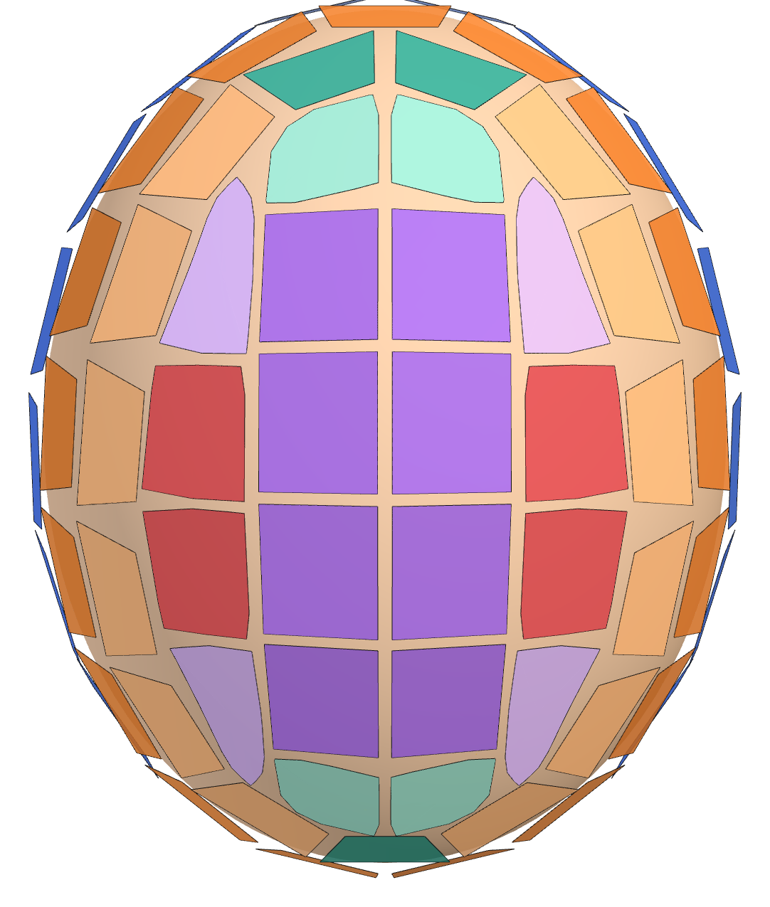
An EEG helmet you can build: 66 flat circuit boards (tiles) in rings round the head like the panels of a cap,
carrying 1,118 gold-plated pogo pins that press through the hair onto the scalp. The 66 tiles are only 9 different
PCBs. A printed PETG shell holds the tiles, a hub at the back gathers the data, five cameras sit in the beanie's cuff,
and a rib-knit beanie goes over all of it. Everything here is generated from code in this repo (exo/); change an
input and rebuild, don't edit the outputs. How the layout was chosen, and what it costs against the alternatives:
studies/tile-cost.
What's in it
| part | what it is | numbers |
|---|---|---|
| tiles | three rings of trapezoids parallel to the cuff, and a top cut into territories; 9 PCB designs, 6 layers, 1.0 mm | 66 tiles, 1,118 contacts |
| pogo pins | one off-the-shelf part on every contact: Kinghelm KH-205580-DZ, 8 mm gold SMD pogo pin, ~2 mm travel, placed by JLC | 1,118 per helmet |
| front end | a TLV333 zero-drift amplifier per contact, gain 101, referenced to the AC-coupled reference contact | 1,118 |
| converters | CH32V203G6U6: a RISC-V microcontroller with a 12-bit ADC, one per ten contacts, oversampled to 500 SPS | 128 |
| chains | tiles daisy-chained four or five to a hub port over the hub's 12-way FPC: power, REF, CLK, SYNC and a UART ring | 16 chains |
| hub | reference and bias, a shared 2.048 MHz clock, 16 tile and 5 camera ports, battery, USB-C, Wi-Fi (the helmet's one radio) | 1 (hub) |
| cameras | RP2350A and an OV2640 wide-angle camera on a 19 × 17 mm board, MJPEG and PDM-mic audio to the hub over the cable (no radio) | 5 (cameras) |
| shell | crown, front band, back band with the hub pod, splice tabs, battery cover; PETG | 5 parts (shell) |
| headband | a 1.6 mm PETG band on a foam pad round the brow and under the occiput, inside the shell; 4 links to it; a micro-ratchet buckle at the nape. Holds the shell down against the pins | EXO-145, 31 N of tension at 150 N of pins (headband) |
| beanie | rib knit with a turned-up cuff; the cameras' lenses through grommets; USB-C eyelet | (beanie) |
To order one: ordering. What it must comply with to be sold, and what that changes in the design: regulatory; the tests, labs, schedule and budget: certification.
How a contact works
Each pogo pin is reflowed onto a pad on the tile's scalp face. Behind it sit two 100k protection resistors, a 220 nF coupling capacitor with a 10M bias to mid-rail, and a TLV333 amplifying the difference between this contact and the reference contact by 101. The reference comes from the hub and is AC-coupled and buffered on every tile in the same way, so electrode offsets of hundreds of millivolts never reach the gain. The amplifier drives a 12-bit converter input directly (1 nF hold capacitor); one LSB is 8 µV at the contact, and 64× oversampling takes it well under the amplifier's own noise. Each CH32V203 scans up to ten contacts, clocked by the hub's 2.048 MHz CLK and aligned by its SYNC, so every converter on the helmet samples together.
Tiles pass their data along a UART ring: the hub's line enters a chain's first tile, runs through each microcontroller in turn and out to the next tile; the last tile's 74LVC1G157 sees nothing on its OUT connector and sends the ring back up the return line to the hub. CLK and SYNC are re-buffered on every tile for the next. See contact boards.
Why the boards look like this
Every contact uses the same pogo pin, so the gap from a tile to the scalp has to stay within the pin's working range (6.2–7.7 mm) across all of its contacts. A flat board over a curved head only manages that over a small area, so the tiles are ~25-30 mm across. Rings parallel to the cuff make every tile in a ring the same trapezoid; the nearly flat top is cut into a symmetric grid of cells, and a cell and its mirror twin share one PCB. Setup fees at JLC are per design, so 9 designs instead of 66 is most of the cost saving (study).
Where it stands
| layout | 66 tiles, 9 designs, 1,118 contacts; every pin 6.29–7.61 mm from the scalp, every pin ≥ 2.40 mm from its board edge, every board ≥ 0.82 mm from its neighbours in 3D (exo.cap_layout) |
| tiles | 9 designs placed, routed and checked: 0 open nets, KiCad DRC 0 errors. Gerbers, BOM and CPL per design and for the two JLC panels, CAP-01 and CAP-02 (boards) |
| hub | placed, routed and checked, Gerbers, BOM and CPL; unchanged by the cap (its ports already carry the chain) |
| cameras | placed, routed and checked, Gerbers, BOM and CPL |
| shell | generated around the tiles: standoffs at every tile's holes, FPC slots and channels for the chains, STL and STEP, with the headband. All 81 checks pass on the current placement and the wired cameras (shell) |
| cost | every part an exact orderable line with its price; JLC fees from their published rules (ordering) |
| signals | simulated, not measured: real EEG replayed and synthetic infills through the tile's signal chain (EEG simulation, run of 2026-11-04 on 1,118 contacts, the contacts' skin-potential drift included). Median contact, with the hub's 8 REF pins: 3.65 µV rms noise (0.5-100 Hz) and 19.2 dB alpha SNR as built, with the two filters the EMI simulation recommends; 5.04 µV and 14.9 dB without them; 11.0 effective bits over the input range |
| pin force | today's 70 g pins push the shell off with 432 N; the headband is designed for 150 N. The soft pin, a preloaded custom spring in the same body, gives 8.5-11.8 g a pin and 113 N (130 N at +15 %); its spec and RFQ are written, nothing sent (pin RFQ). A bench finds the lowest force that reads through hair and chooses the spring by a stated rule; not run yet (pin-force bench) |
Watching the soft parts live
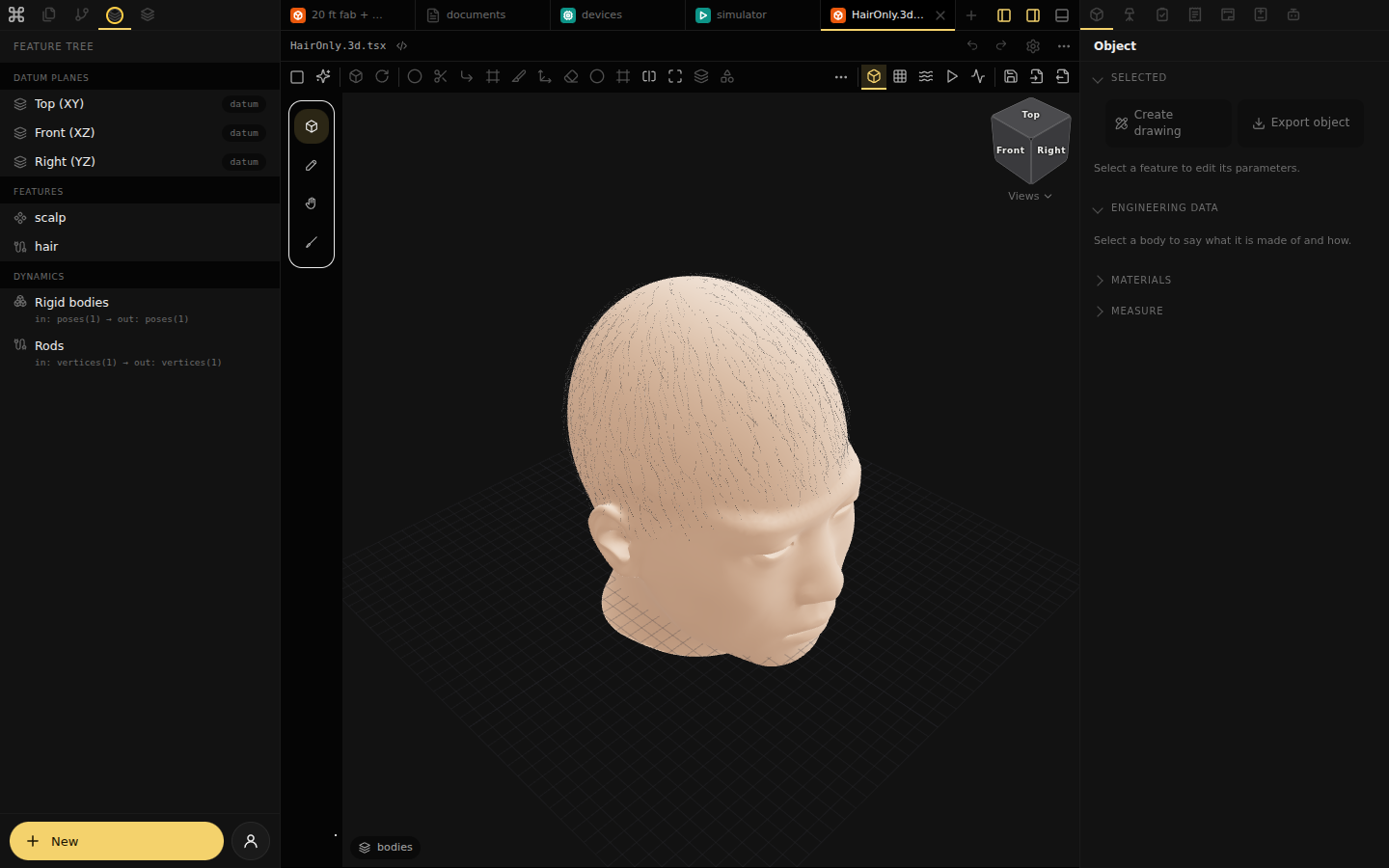
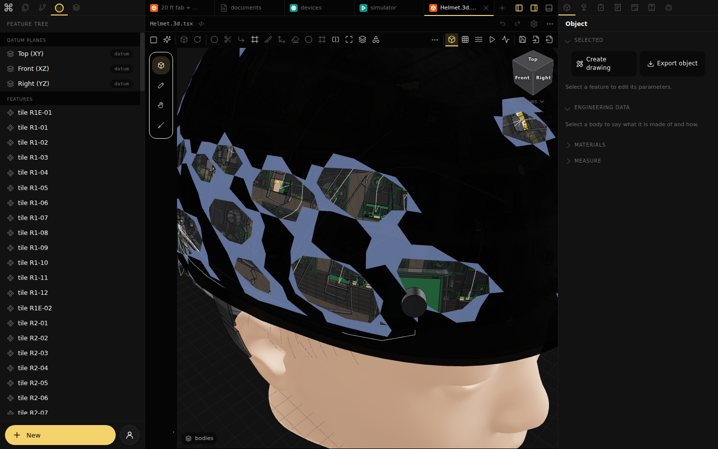
The hair, the flat cables and the beanie are simulated in CommandAGI's 3D editor while it is open, not only drawn
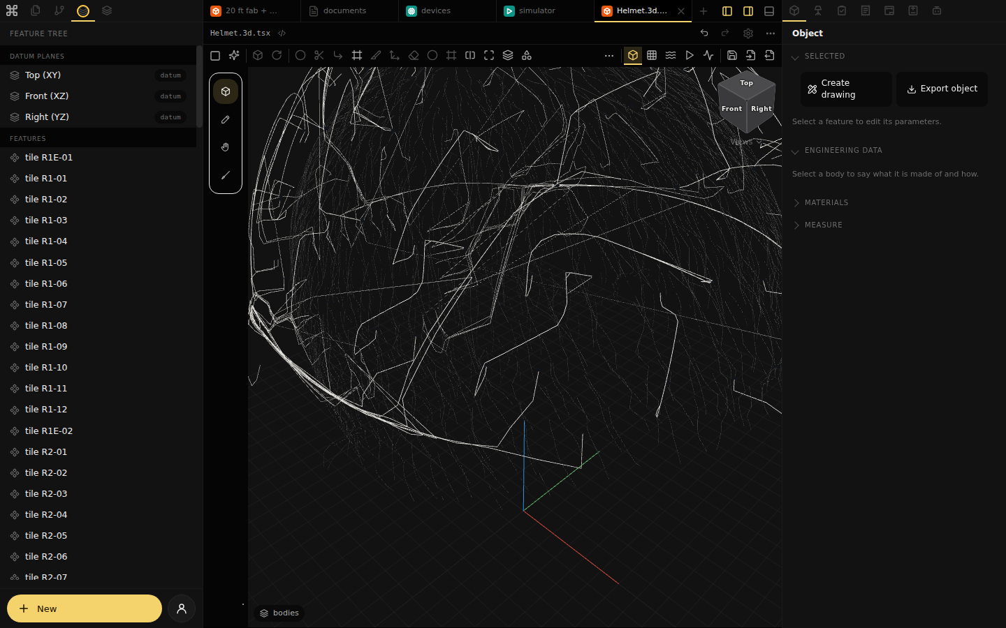
(cad/Helmet.3d.tsx, written by exo/cad_doc.py and exo/wearer.py). The hair is one rod of 800 guide strands of 8
points (cad/models/hair-guides.obj, each root held on the scalp where it grows), and it meets the scalp, the 66
tiles' pins and the headband. Each of the 71 cables is a ribbon rod (6.5 × 0.15 mm, cad/materials/rods.csv) from
the routed path in its channel (cad/models/cables.json), its two ends inserted in <port>s on the connectors of the
placed tile, hub or camera; it meets the shell and the headband. The beanie is a cloth pinned at its hem. All three
run with the editor ("Always" in the Studio tab's Dynamics panel), and a press on a hair, a cable or the knit pulls
it.
To watch it: open cad/Helmet.3d.tsx (or exocortex.dashboard.tsx) in a CommandAGI workbench at its main, with
the 3D service installed (pnpm commandagi threed install) so the placed STEP solids are built and the cables'
ports find their bodies. Use a browser with a GPU: on gb10 with Chrome on its GPU (ANGLE over Vulkan) the hair alone
draws at 23 ms a frame, and the whole helmet with every rod and the cloth at 145 ms, its simulated time about 3 % of
real time. In software WebGL the whole helmet takes 3-10 s a frame. The hair then rests where it is laid, on the scalp
and clear of every pin, and the cables lie along their channels. On 2026-11-04 CommandAGI's main still stops it: a
64,000-triangle scalp overflows the engine's stack when a rod rests on it, the beanie does not drape (part of the
knit and 7 cables are NaN in the page), and 71 ribbons with their own up make 66 rod sets that each check every
other. The CommandAGI section of the README says what each is and what the measurements were.
| the hair alone on the scalp, live | the helmet live (the knit drawn at rest) | the rods alone: hair and cables |
|---|---|---|
 |
 |
 |
Nothing has been built or measured on a head yet: contact impedance and noise on hair, motion artefacts, pin force and comfort, fault injection, clock skew along the chains and EMC all need a bench.